Applications to Additive Manufacturing
Calculate the following as a function of material chemistry and temperature:
Application Examples
Using Printability Maps to Reduce the Risks of Defects
Printability maps allow users to plot the likelihood of possible defects that occur during additive manufacturing – keyholing, lack of fusion, and balling. These defects occur based on the speed and power used during the AM process, so printability maps allow you to reduce the risks of these defects by showing the speed and power settings that are optimal (the white area in the image), allowing you to calibrate your system to avoid these issues.
The AM Module in Thermo-Calc makes it possible for users to create printability maps. Printability maps show that a conduction mode melt pool is needed for a fully dense melt pool and to avoid keyholing defects, common in keyhole type melt pools. The plot here shows such a map for a 316L stainless steel performed using a calibrated gaussian heat source. All the experimental variations of power (40-100 W) and scan speed (400-3000 mm/s) are plotted to generate printability maps. The printability map is then overlaid with experimental data from Hu et al., 2019. ‘K’ denotes keyhole mode and ‘C’ denotes conduction mode for a melt pool.
You can read more about printability maps in Thermo-Calc and watch a video about how we set them up and interpret the results in our blog post, Avoid Defects in the Powder Bed Fusion Process with Printability Maps.

Predicting Melt Pool Size
Knowing how the process parameters affect the melt pool size is key in additive manufacturing to get a robust and homogeneous build. With the Additive Manufacturing Module in Thermo-Calc, you can simulate the steady state behavior of the melt pool for any material and process parameter. Grange et al. performed a range of single-track experiments on Inconel 738LC with a composition of Ni-15.8 Cr-8.6 Co-2.7 W-3.3 Ti-3.6 Al-1.8 Ta-1.8 Mo-0.04 Fe-0.8 Nb-0.002 Mn-0.1 C Mass % and measured the width and depth of the melt pool.
The single-track experiments with lowest (0.24) and highest (0.47) ratio between Power and scan speed (P/v) were chosen to optimize the parameters for the double ellipsoid heat source, also known as Goldak heat source. Many simulations were run, with varying Heat Source parameters, until good agreement with Grange’s melt pool dimensions were obtained. A linear relation for each Heat source parameter was then applied, as a function of P/v, to simulate all cases in Grange et al.
The comparison between experimental and predicted melt pool sizes are shown in the figures here. As seen, the optimized parameters give a very good agreement between predicted and experimental melt pool dimensions for all process cases, although it was only optimized using 2 of them.

Improving Finite Element Modeling with CALPHAD Data
The accuracy of finite element (FE) simulations depends in part on the material property data used by the code. For example, to predict the size, shape, and temperature of the laser melt pool, FE codes need the latent heat and heat capacity of the material. Handbooks are a common source of data, but these typically do not have temperature-dependent data for industrial alloys or data for novel materials. Temperature-dependent data can be calculated using Thermo-Calc for specific chemical compositions of interest.
These figures show a comparison of handbook values and CALPHAD calculated values of Cp (top) and ΔH (bottom) for a 316L Stainless Steel (recalculated from Smith et al. Comput. Mech. 2016).

Capturing the Effects of Rapid Solidification
Rapid solidification, typical of additive manufacturing processes, can lead to solute trapping where solute may be incorporated into the solid phase at a concentration significantly different from that predicted by equilibrium thermodynamics. These effects influence microsegregation, solidification morphology, and the emergent microstructure length scales.
The Scheil Solidification Simulation Calculator in Thermo-Calc includes a model that considers solute trapping in the primary phase for calculations that have a high solidification speed, the Solute Trapping model. The model is based on the main assumption that the primary phase is the only dendrite forming phase within which solute trapping is induced by high solidification speed. The resulting solute trapping also affects composition and amount of other solid phases.
This figure shows a Scheil Solidification Simulation for an Al-Si-Mg alloy using the Solute Trapping model compared with a Classic Scheil Solidification Simulation and equilibrium. The plot shows that the Solute Trapping model is closer to equilibrium as the solidification progresses.

Printing High-Reflectivity Materials (AlSi10Mg)
Most laser-based additive manufacturing processes use a red laser (wavelength : 1.06 µm) where the absorptivity of some metals, such as Al and Cu, is quite high (Kirihara, 2021). Al- alloys also have low viscosity as compared to Fe- or Ni-based alloys. The low viscosity in combination with high fluid flow rates can result in turbulent flows. Additionally, some Al-alloys, such as Al-Si based alloys, solidify with a eutectic microstructure (Thijs et al.). This eutectic microstructure becomes finer or coarser depending on solidification conditions such as cooling rate of solidification front. Due to rapid solidification conditions in additive manufacturing, solute trapping occurs, which leads to increased solubility of Si in FCC-Al (~3 at% instead of 1.5 at% in classic Scheil).
The Solute Trapping Model in our Scheil Calculator can account for increased solute trapping in the primary phase for high solidification speeds, often seen during the AM process. Thermo-Calc also allows users to account for phase-interface scattering (to account for microsegregations, eutectic solidification) before setting up calculations in the AM Module.
The first plot here shows the increased solubility of Si in FCC-Al due to rapid solidification conditions, which is captured by the Scheil Solute Trapping Model in Thermo-Calc. The second is a parity plot based on Bogdonova et al., 2024, wherein we represent the experimental to calculated melt pool dimensions calculated for an AlSi10Mg alloy printed by powder bed fusion-laser beam (PBF-LB) process.

Predicting Optimal Post-build Heat Treatments
During precipitation heat treatment of additively manufactured 625 parts, the deleterious delta phase can precipitate faster than in wrought 625, leading to degradation of properties. Zhang et al (Acta Mater. 2018) have used Thermo-Calc and the Precipitation Module (TC-PRISMA) to predict the precipitation kinetics of the delta phase for nominal feedstock compositions, as well as the compositions measured at dendrite boundaries.
Both simulations, shown in the figures, predict that a stable MC carbide forms, followed by some gamma double prime (γ″). Delta (δ) phase then forms at the expense of the γ″. Because of segregation during solidification, γ″ and δ phase both precipitate much more quickly in the interdendritic region due to the increased Nb and Mo. Delta phase is predicted to start forming around 1 hour, compared with 10 hours for the wrought material. These calculations give insight to the reason why the conventional stress-relief heat treatment is not suitable, and can be used to identify a suitable heat treatment to both homogenize and stress relieve the part, while avoiding deleterious phases.

Predicting Primary Grain Microstructure upon Rapid Solidification
When metallic alloys solidify, the resulting primary grain microstructure can be columnar or equiaxed depending on the solidification conditions imposed. These conditions can be characterised by parameters such as the thermal gradient (G) and solidification growth rate (v) of the solidifying melt. The Columnar to Equiaxed Transition (CET) Property Model, which is available as a General Property Model in Thermo-Calc, uses these conditions to predict the fraction of equiaxed grains that correlates with a certain solidification condition.
Users can plot the thermal gradient and solidification growth rate as a scatter plot directly from the AM Module. These results can then be overlaid over the results from the CET General Property Model to identify if the melt pool will solidify with columnar grains or equiaxed grains. The plot here shows an example for an IN718 alloy using AM Module plotting solidification rate and thermal gradient in a log-log plot. This plot is then overlaid on a CET Model based on a similarly produced IN718 alloy (Polonsky, 2020) to demarcate the position for amount of equiaxed fraction of grains. The AM calculation shows that most of the melt pool (the points below the purple line) solidifies in a fully columnar solidification microstructure, which is typical for such materials.

Predicting Microsegregation Profile upon Rapid Solidification
High cooling rates in additive manufacturing processes make it possible to generate novel microstructures. In one such case, for a hot work tool steel produced by PBF-LB process, Chou et al. 2021, results showed that the solidification conditions in the process enabled suppression of ferrite and solidification of austenite phase directly with elemental microsegregation in inter-cellular regions.
This microsegregation is difficult to characterize and often requires advanced microscopy to analyse the chemistry. With Thermo-Calc, users can take probe data (temperature-time) from an AM Module simulation to use as an input into the Diffusion Module (DICTRA). This can then capture the microsegregation of elements as a function of distance, thereby simulating the expected solidification microstructure.
In the example shown here , the AM Module is used to define the process with similar processing parameters. The temperature-time data from a probe is then used as an input to the Diffusion Module (DICTRA), which then simulates the segregation of solutes in the inter-cellular regions upon rapid solidification. The simulated cellular segregation profile is seen to be in good agreement with experimental values.


Powder Bed Fusion
Additive Manufacturing Module
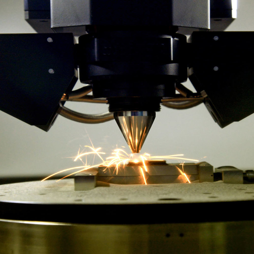
The Additive Manufacturing Module is an Add-on Module in Thermo-Calc that allows users to model the Powder Bed Fusion process. Special focus has been to have a unified treatment of alloy dependent material properties and process parameters when solving the multiphysics problem of a moving heat source that melts and solidifies metal powder.
Learn More about Applications to Additive Manufacturing
Improve Your AM Simulations: Learn How to Use the Latest Features in the Additive Manufacturing Module
AlloyGPT: an agent-based LLM framework for the design of additively manufactured structural alloys in extreme environments
Accelerated Design of Printable Superalloys for Additive Manufacturing: CALPHAD- and ICME-based Approach
Thermodynamic and Kinetic Simulations on Joining and Additive Manufacturing Processes for an ICME Framework
Applications of CALPHAD-based tools to additive manufacturing
Development of Non-Equilibrium Thermodynamic Tools for Additive Manufacturing
Degradation of AlSi10Mg powder during laser based powder bed fusion processing
An integrated computational materials engineering-anchored closed-loop method for design of aluminum alloys for additive manufacturing
Application of finite element, phase-field, and CALPHAD-based methods to additive manufacturing of Ni-based superalloys
Additive Manufacturing of 17-4 PH Stainless Steel: Post-processing Heat Treatment to Achieve Uniform Reproducible Microstructure
Toward an integrated computational system for describing the additive manufacturing process for metallic materials
Effect of the Process Atmosphere Composition on Alloy 718 Produced by Laser Powder Bed Fusion
Modelling of additive manufacturability of nickel-based superalloys for laser powder bed fusion


