About the Additive Manufacturing Module
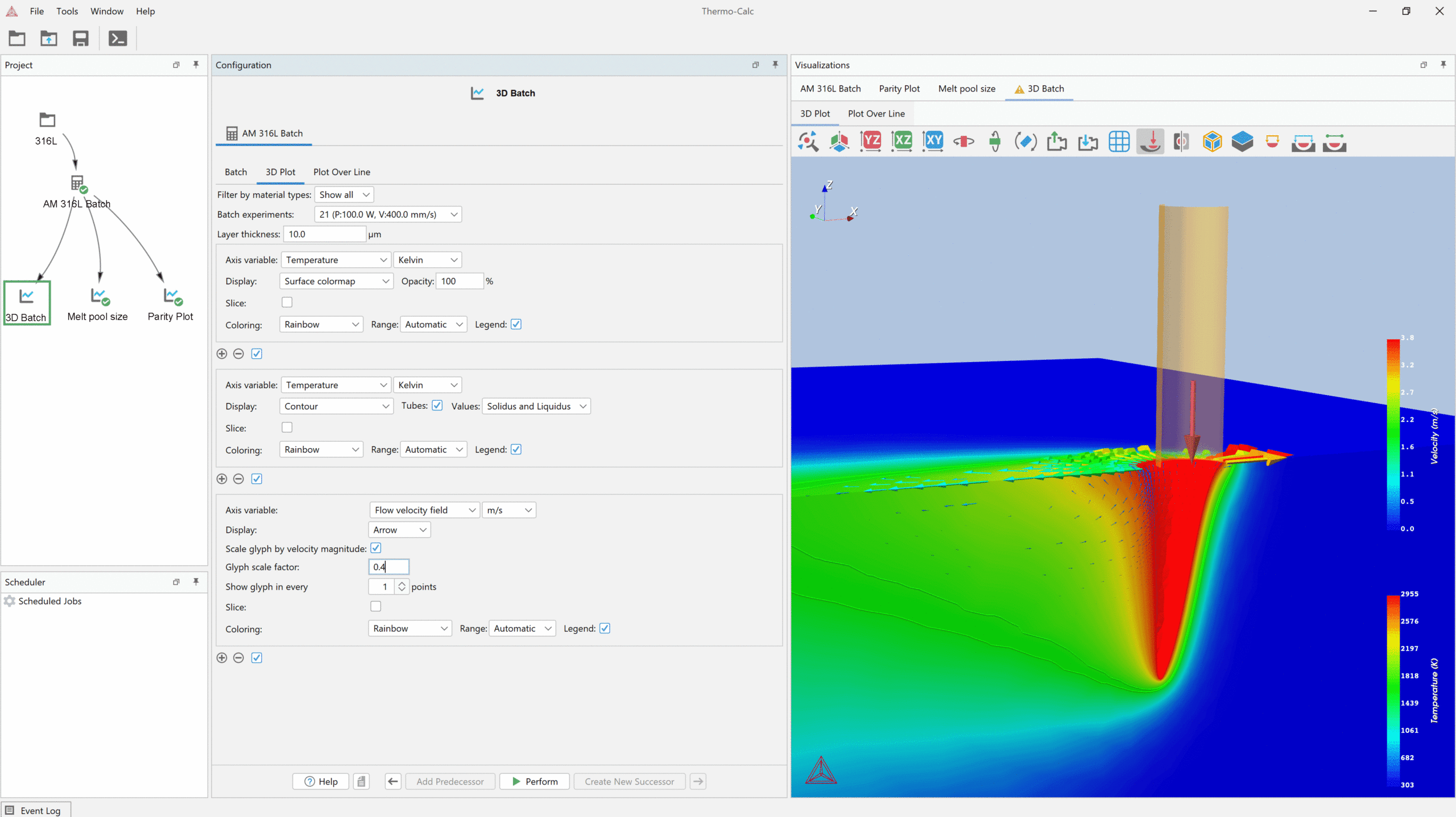
A screenshot of the Additive Manufacturing Module showing the results of a steady state calculation for the material SS316L. A keyhole can be seen formed just below the location of the heat source.
Calculate Any Alloy
Simulate Laser Powder Bed Fusion and Electron Beam Melting
Three Simulation Modes to Solve a Range of Problems
Different Calculation Types for Accurate Process Simulations
The Additive Manufacturing Module Allows You to Calculate
Steady-State
Transient and Transient with Heat Source from Steady State
Printability Maps to Avoid Defects
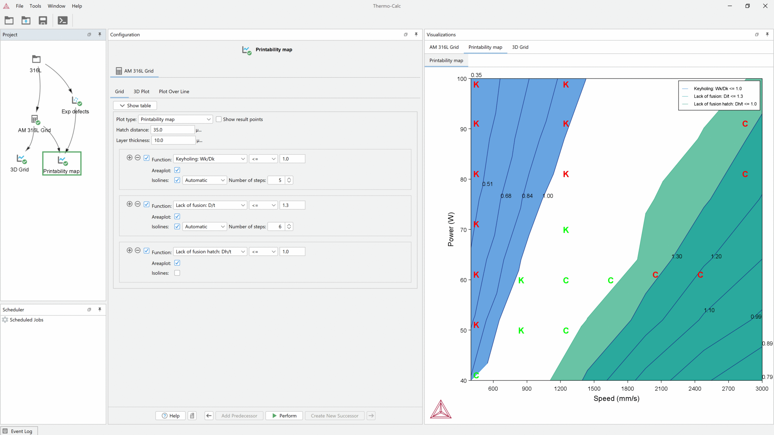
A printability map calculated in the AM Module for the material 316L showing the power and scan speeds that are likely to result in keyholing (blue area) and lack of fusion (green area). The white area shows the power and scan speeds that are optimal to reduce the risk of these defects.
Compare Results to Experimental Data
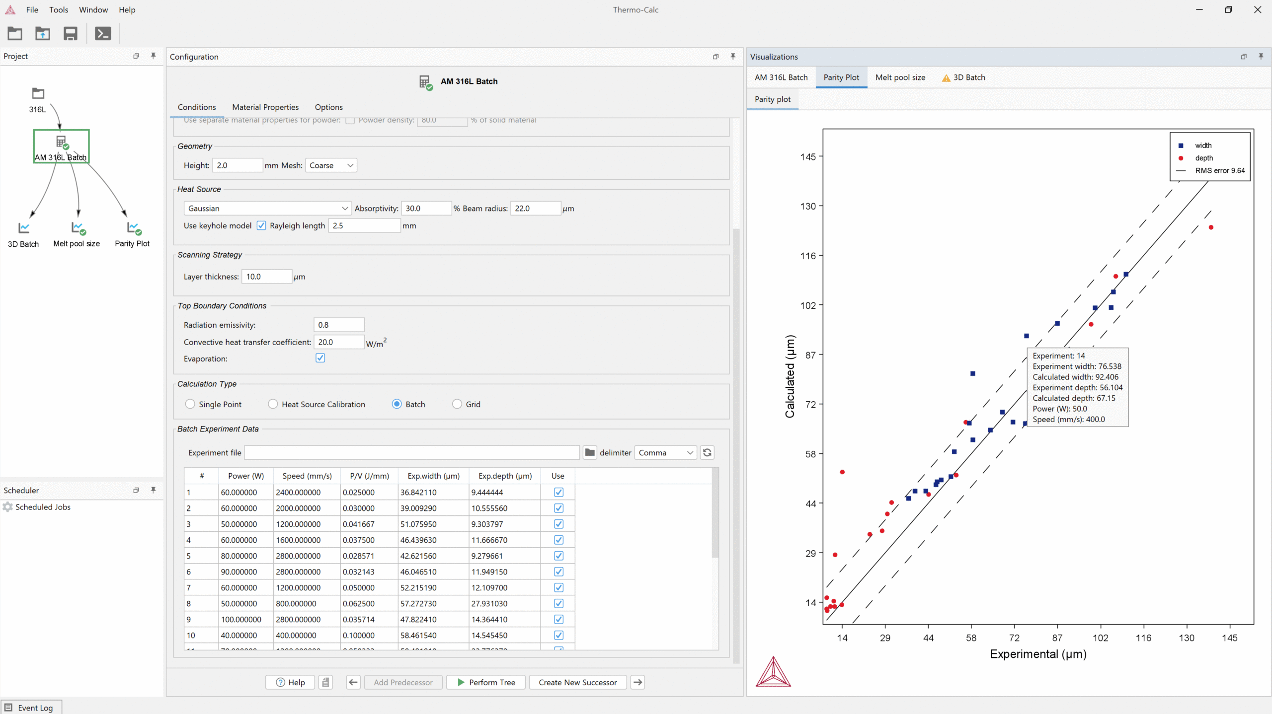
A parity plot generated in the AM Module comparing calculated and experimental results of how power and scan speed affect melt pool dimensions. The AM Module allows users to input power and scan speed data and experimental results from a file and compare them to calculated results using the Batch Calculation type.
Easy Workflow
Predict the Microstructure of an Alloy
Predicting Microstructure in the Diffusion Module (DICTRA)
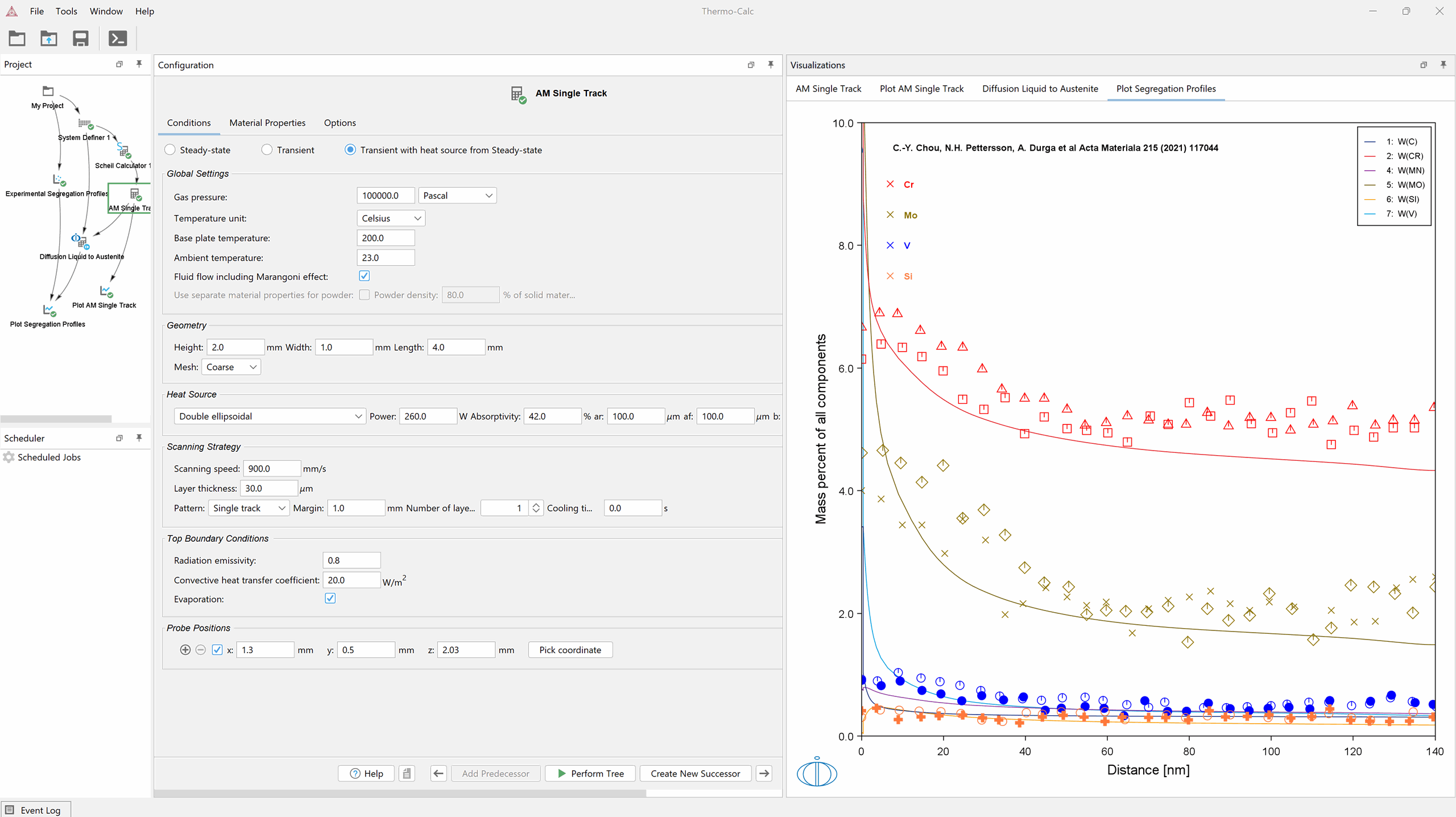
Simulated segregation profile with overlaid experimental STEM-EDS line scans from C.-Y. Chou et al. [2021Cho]. The calculation is an example of coupling the Additive Manufacturing Module with the Diffusion Module (DICTRA).
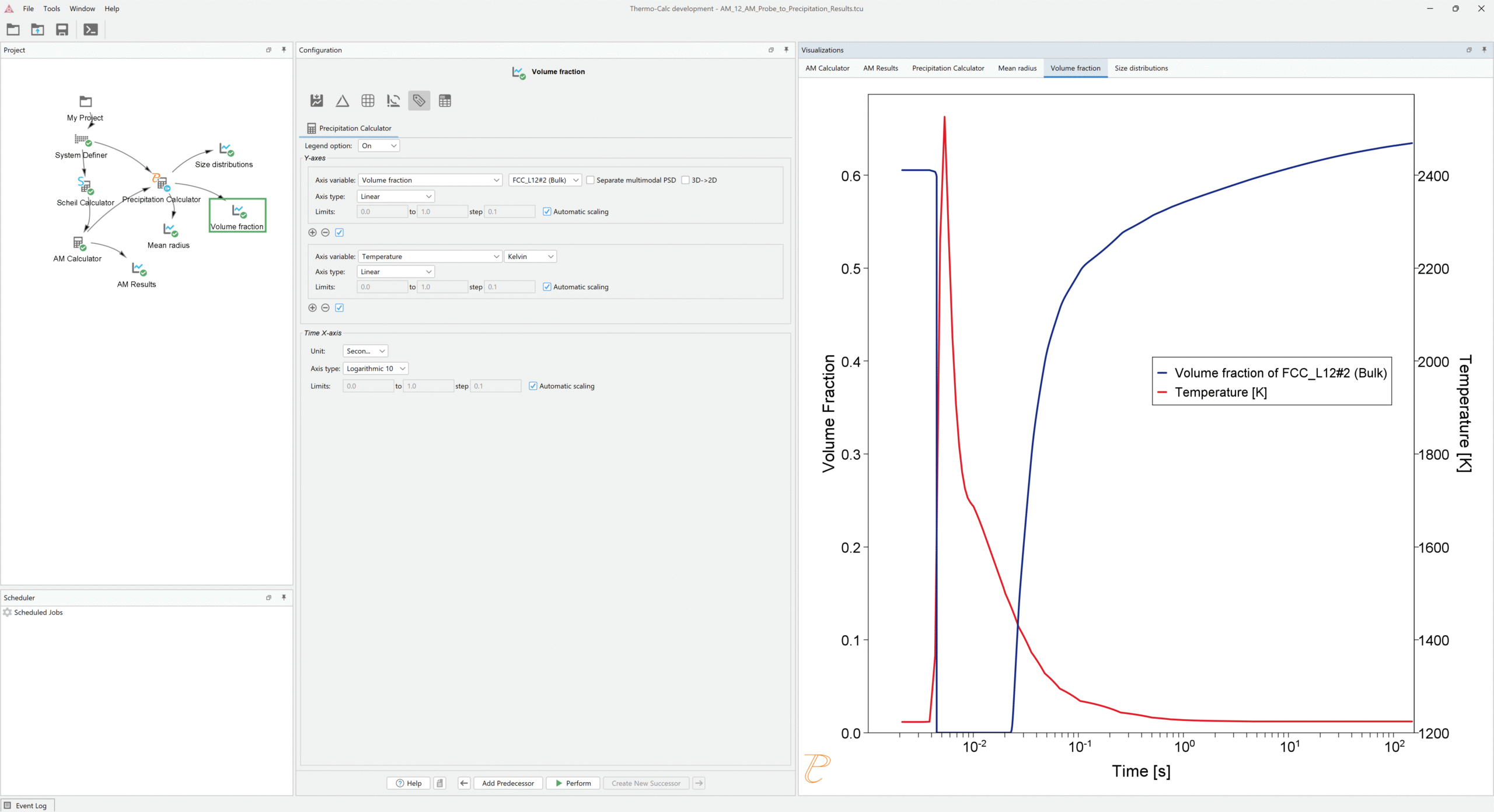
Simulated incipient melting of the large precipitates in the powder, and the reprecipitation after a single pass of an electron beam. The change in volume fraction of the precipitate phase as a function of time is shown on the left axis, with the time-temperature history shown on the right axis. The sudden drop in volume fraction is a result of incipient melting. The volume fraction increases upon reprecipitation once the material has resolidified and sufficient undercooling has been reached. This example demonstrates how probes calculated in an AM simulation can be directly input into the Precipitation Module (TC-PRISMA) using options designed for AM conditions.
Predicting Microstructure using the CET Model
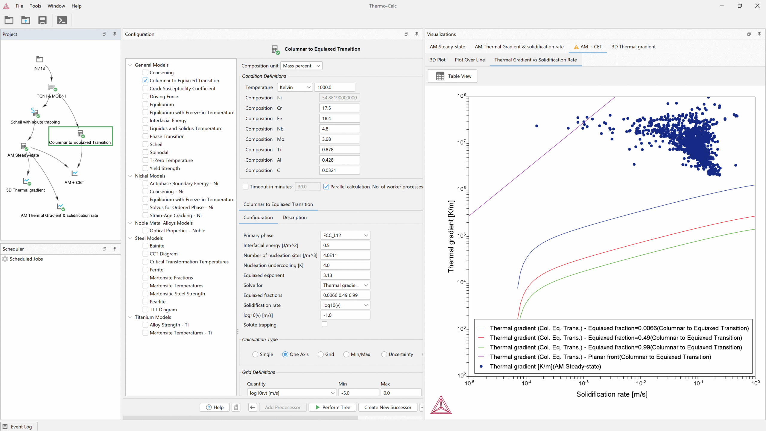
Thermal gradient vs solidification rate for IN718. The blue, red, and green lines show the increasing equiaxed fraction from the CET Model and the points show the solidification conditions at the melt pool calculated with the AM Module. When overlaid, it can be seen that nearly all the points (those below the purple line) exist in a fully columnar region. The calculation is an example of overlaying results from the Additive Manufacturing Module over CET results.
Integrates with TC-Python
Export Results for Further Analysis
Databases

Upcoming Training Courses
Additive Manufacturing Module (AM Module) Training
The Additive Manufacturing Module (AM Module) Training is designed for beginners with no prior knowledge required. This hands-on course covers the Powder Bed Fusion process, including temperature distribution, melt pool geometry, and defect generation, as well as integration with other Thermo-Calc modules. It features teacher-led exercises, Q&A sessions, and interactive learning in English, with all necessary materials provided in advance.
We schedule courses two to three times per year, check out the course pages to see if we currently have courses scheduled.
Learn More about the Additive Manufacturing Module
Improve Your AM Simulations: Learn How to Use the Latest Features in the Additive Manufacturing Module
A collection of videos demonstrating the capabilities of the Additive Manufacturing Module.
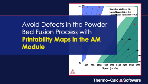
Avoid Defects in the Powder Bed Fusion Process with Printability Maps
